


 русский
  Español
  中文简体
中文简体
Industry News
Home / News / Industry News / Complete Engineering Guide to Industrial Vehicles Instruments: Selecting Analog vs Digital Systems for Heavy Equipment
Complete Engineering Guide to Industrial Vehicles Instruments: Selecting Analog vs Digital Systems for Heavy Equipment
Admin 2026-05-27Content
- 1 1. Introduction to Heavy Duty Instrumentation Architecture
- 2 2. Performance, Precision, and Accuracy Matrix
- 3 3. Environmental Endurance and Physical Reliability
- 4 4. Systems Integration, Signal Communication, and Network Telematics
- 5 5. Economic Assessment and Product Life Cycle Cost Analysis
- 6 6. Detailed Mechanical Parameter Tracking Comparisons
- 7 7. Comparative Operational Performance Summary
- 8 FAQs
- 8.1 Q1: Why do mechanical analog instruments still hold a significant market presence despite the precision advantages of digital displays?
- 8.2 Q2: How do digital instruments mitigate the display lag and pixel ghosting caused by extreme cold environments?
- 8.3 Q3: What is parallax error, and how exactly does it compromise operator safety in heavy machinery applications?
- 8.4 Q4: Can digital instruments be integrated into older industrial vehicles that utilize traditional mechanical sending units?
- 8.5 Q5: How do the long-term maintenance costs of analog instrument groups compare to single-screen digital display clusters?
- 9 References and Technical Standards
1. Introduction to Heavy Duty Instrumentation Architecture
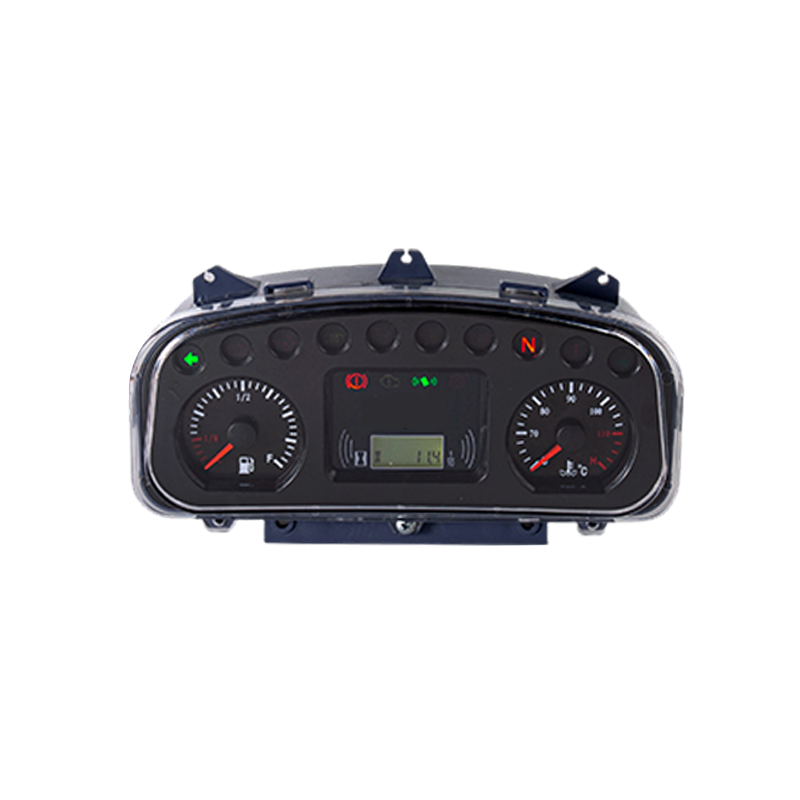
Industrial vehicle operations depend on clear, accurate information from the machine core to the dashboard layout. For engineers, fleet supervisors, and component procurement managers, choosing between analog indicators and digital display nodes involves balancing reliability, signal precision, operational environment dynamics, and long-term asset management. This document provides a complete technical analysis of modern instrument groups used across construction, agricultural, mining, and material handling systems.
To select the proper platform, one must first analyze how mechanical and electrical forces transform into visual indicators on an operator console.
1.1 Mechanical and Engineering Principles of Analog Indicators
Analog instruments use direct physical coupling or basic electrical signal processing to move a physical pointer across a printed dial face.
Mechanical Bourdon tube gauges use a curved, flattened bronze or stainless steel tube sealed at one end. As internal fluid or air pressure increases, the tube straightens. This small movement is magnified by a gear mechanism, turning the pointer shaft.
Bi-metallic and air-core gauges provide thermal tracking, such as engine coolant temperature. Analog systems rely on bi-metallic strips that bend when heated by an electrical current from a thermistor sensor. Air-core instruments use orthogonal electrical coils creating a magnetic field that positions a permanent magnet rotor attached to the indicator needle.
1.2 Engineering Architecture of Electronic Digital Systems
Digital systems replace moving components with solid-state silicon architectures.
A piezoresistive pressure transducer or an RTD (Resistance Temperature Detector) generates a continuous, analog low-voltage signal based on environmental inputs.
The raw microvolt output passes through a signal conditioning amplifier to filter out electromagnetic interference. An ADC (Analog-to-Digital Converter) then samples this voltage at high rates, converting the physical measurement into binary values.
An integrated microcontroller processes the data stream, applies temperature compensation algorithms, and outputs numerical figures or graphic bars onto a Liquid Crystal Display (LCD) or Thin Film Transistor (TFT) screen.
2. Performance, Precision, and Accuracy Matrix
Measurement discrepancies directly impact component lifespans. Analog dials are limited by reading interpretation errors and physical design constraints. Parallax error happens when an equipment operator reads a dial from an angle, making the needle appear to align with a different scale increment. Furthermore, analog scales require operators to visually estimate values between printed hash lines, reducing consistent accuracy.
Digital modules eliminate these variable human errors by showing exact numerical text. Internally, solid-state sensors maintain tight accuracy boundaries across their entire scale, while mechanical gears struggle to maintain precision at the extreme high and low ends of their range.
| Performance Attribute | Mechanical Analog Instruments | Microprocessor Digital Systems |
|---|---|---|
| Standard Accuracy Class | Plus or minus 2.0 percent to 5.0 percent of full scale | Plus or minus 0.1 percent to 0.5 percent of full scale |
| Resolution Limits | Limited by graduation marks and dial diameter | Configurable decimal output based on bit depth |
| Reading Interpretation Errors | Prone to parallax distortion and estimation errors | Zero interpretation errors via clear numerical output |
| Response Delays | Delayed by mechanical inertia and fluid dampening | Real-time electronic updates under 10 milliseconds |
| Over-Pressure Protection | Mechanical deformation occurs beyond 130 percent load | Electronic sensors handle up to 200 percent spike capacity |
| Unit Adjustments | Fixed single unit printed on the physical dial face | Field-switchable configurations (Metric or Imperial) |
3. Environmental Endurance and Physical Reliability
The operating environment of heavy industrial machinery includes high vibrations, physical impacts, and extreme temperatures. These factors challenge the long-term reliability of any installation.
3.1 Vibration and Shock Dissipation Performance
Mechanical dials are highly vulnerable to vibration. Continuous shaking accelerates wear on small brass pinions and internal hairsprings. This causes pointer flutter, which makes dials difficult to read and leads to calibration drift. To counter this, heavy machinery analog lines must use glycerin or silicone fluid fillings to dampen internal movements.
Digital instruments use solid-state surface-mount components soldered onto rugged printed circuit boards (PCBs). Without moving components, these devices naturally resist intense harmonic vibrations and heavy physical impacts.
3.2 Thermal Performance and Extreme Weather Adaptation
Temperature management shows a distinct trade-off between the two designs:
- Analog Gauges: These run reliably from minus 40 degrees Celsius to over 80 degrees Celsius without losing display clarity, though internal spring properties can shift slightly in extreme heat.
- Digital Displays: LCD and TFT screens contain fluid layers that can freeze or react slowly in extreme sub-zero weather, causing display ghosting or slow refresh speeds. Industrial digital modules require integrated, automatic internal heating elements to keep pixels responsive during cold weather start-ups.
4. Systems Integration, Signal Communication, and Network Telematics
Modern machines require connected components that communicate across a shared network. Analog gauges operate as isolated, one-way displays. They receive a sensor input and show it to the operator, but cannot share that data with onboard diagnostic modules or telematics boxes.
Digital gauge configurations handle complex multi-protocol tasks. Built-in microcontrollers gather operational data and broadcast it across the machine network using standardized Controller Area Network (CAN bus) communication protocols. This allows a single pressure sensor reading to simultaneously inform the cabin display, trigger an engine control module safety shutdown, and send an alert to a fleet management portal.
The data stream operates down a structured electronic pathway:
- Step One: The primary sensor detects pressure or temperature and transmits a raw voltage signal.
- Step Two: The digital instrument cluster node processes the incoming voltage and translates it into data packets.
- Step Three: The node broadcasts this numerical data across the CAN bus network.
- Step Four: Multiple vehicle endpoints receive the data concurrently. The onboard cabin display shows a visual alert, the engine safety system initiates a shutdown if limits are exceeded, and the wireless gateway sends updates to the remote fleet management portal.
5. Economic Assessment and Product Life Cycle Cost Analysis
From an economic perspective, analog instruments require a lower initial hardware purchase. However, they need manual calibration over time, have a higher failure rate under high vibration, and require running independent, heavy wiring bundles for every single gauge.
Digital modules cost more upfront but lower long-term expenses. They streamline dashboard designs, support automatic software self-calibration, and reduce wire harness weight by routing multiple signals over a single pair of network cables.
5.1 Installation and Wiring Complexity Analysis
Each analog unit requires dedicated point-to-point wiring from the measurement source directly to the machine dashboard. This creates massive, heavy wire bundles that are difficult to route, troubleshoot, and repair when physical fatigue occurs.
Digital instrument clusters solve this issue by utilizing shared communication networks. Dozens of mechanical parameters travel down a single pair of twisted wires, drastically reducing the physical footprint of the vehicle wiring harness.
5.2 Long Term Calibration Maintenance Cost
Mechanical instruments experience structural drifting due to spring fatigue and gear wear. To maintain accurate readings, field technicians must perform manual adjustments using calibration equipment every few months.
Digital modules utilize automated lookup tables and software algorithms to adjust for sensor age and thermal drift, completely removing the labor costs associated with manual system recalibration.
6. Detailed Mechanical Parameter Tracking Comparisons
Industrial vehicle groups require precise tracking of distinct operational parameters. Choosing between analog and digital components varies significantly depending on the specific engine metric being monitored.
6.1 Rotational Speed and Engine RPM Tracking
Tachometers represent a vital readout for heavy machinery operators who must maintain engine speeds within a safe peak torque band.
Analog tachometers use magnetic induction principles where a rotating shaft spins a permanent magnet inside an aluminum cup, generating torque against a return spring. This method provides smooth, sweeping pointer movements that help operators monitor rate changes via peripheral vision.
Digital tachometers use magnetic pickup sensors to count engine flywheel teeth. The microchip calculates the pulse frequency and converts it into a distinct numerical readout. This guarantees perfect reading accuracy down to a single RPM, allowing operators to set precise idle rates and optimize fuel usage.
6.2 Hydraulic Fluid and Engine Oil Pressure Monitoring
Pressure monitoring requires immediate response times to prevent catastrophic mechanical lockups.
Mechanical pressure gauges must route high pressure lines filled with oil or hydraulic fluid directly into the operator cabin. If a physical rupture occurs inside the dashboard assembly, pressurized hot fluids pose a direct safety risk to the vehicle operator.
Digital pressure monitors eliminate fluid lines in the cabin by using solid-state sensors located directly at the engine block. The sensor converts fluid pressure into electronic data, sending safe low-voltage signals or CAN bus packets to the dashboard display, preventing operator exposure to hazardous high-pressure fluids.
6.3 Thermal Management and Engine Coolant Temperature Tracking
Tracking thermal variations prevents heavy vehicle engine blocks from overheating during intense duty cycles.
Analog temperature gauges utilize mechanical capillary tubes filled with volatile fluids that expand when heated, physically pushing the pointer needle. These tubes are highly vulnerable to physical kinking during installation and cannot be easily repaired if damaged.
Digital temperature gauges utilize electrical resistance thermistors that experience distinct electrical changes as ambient temperatures shift. The processing unit interprets these changes and displays color coded warning zones on screen, allowing the system to trigger automated alarm buzzers long before mechanical components warp from excessive heat.
7. Comparative Operational Performance Summary
To assist system engineers and purchasing managers in selecting the ideal instrumentation setup for heavy equipment manufacturing, the following data summarizes performance metrics under standard operating conditions.
| Engineering Parameter | Mechanical Analog Assemblies | Modernized Digital Modules |
|---|---|---|
| Mean Time Between Failures | Approximately 5000 operating hours | Greater than 20000 operating hours |
| Configuration Flexibility | Fixed single scale setup | Software programmable layouts |
| Enclosure Protection Rating | Standard IP65 water resistance | Advanced IP67 or IP69K liquid ingress protection |
| Voltage Supply Requirements | None required for mechanical lines | Constant 9 to 32 Volt direct current systems |
| Diagnostic Code Output | No physical error logging capabilities | Full SAE J1939 active fault code logging |
| Diagnostics Hardware Needs | Requires physical pressure testing pumps | Plugs directly into electronic scan tools |
FAQs
Q1: Why do mechanical analog instruments still hold a significant market presence despite the precision advantages of digital displays?
Analog instruments remain popular due to their instant, at-a-glance readability and lack of power dependency. Heavy vehicle operators can monitor a needle position using peripheral vision without reading specific numbers; a needle pointing straight up tells them the cooling system is running normally. Additionally, mechanical gauges do not need electrical power to display pressure or vacuum levels. This ensures continuous safety monitoring even during a complete machine electrical failure.
Q2: How do digital instruments mitigate the display lag and pixel ghosting caused by extreme cold environments?
Industrial-grade digital displays use automated, built-in thermal management systems. The controller monitors an internal temperature sensor; if ambient conditions drop below zero degrees Celsius, it activates thin polyimide heating layers placed behind the LCD matrix. This keeps the liquid crystal fluid within its optimal operating temperature range, preventing sluggish pixel refreshes and maintaining screen responsiveness during winter operation.
Q3: What is parallax error, and how exactly does it compromise operator safety in heavy machinery applications?
Parallax error is a visual distortion that happens when an operator reads an analog gauge dial from an offset angle rather than looking straight at it. The physical gap between the needle and the printed scale background causes the pointer to line up with a different measurement tick from the side view. In heavy vehicles like mining trucks or excavators, this distortion can cause an operator to misread oil pressures or engine temperatures, leading to missed warnings and preventable component failures. Digital numerical readouts completely eliminate this physical gap and the resulting human error.
Q4: Can digital instruments be integrated into older industrial vehicles that utilize traditional mechanical sending units?
Yes, older equipment can be retrofitted using inline signal conversion modules. A physical pressure line or mechanical rotation cable can be connected to an intermediate sensor housing that converts mechanical movement or variable resistance into a digital pulse-width modulation or voltage output. This processed signal can then be read by modern digital instrument clusters without requiring a full engine overhaul.
Q5: How do the long-term maintenance costs of analog instrument groups compare to single-screen digital display clusters?
While a single analog gauge is inexpensive to replace if broken, an array of 8 to 10 independent dials requires a complex web of individual sending wires, fluid lines, and mounting brackets, which increases troubleshooting labor over time. A unified digital display cluster consolidates these lines into a streamlined layout. It features automated calibration tracking and has no internal gears to wear out from engine vibration, resulting in lower total maintenance costs over the service life of the machine.
References and Technical Standards
- Society of Automotive Engineers (SAE) J1399: This standard defines accuracy thresholds, vibration profiles, and performance testing criteria for heavy equipment rotational monitoring tools.
- International Organization for Standardization (ISO) 2575: This specification sets international standards for visual indicators, icons, and display layouts used on agricultural and heavy industrial equipment dashboards.
- SAE J1939 Architecture: The core technical standard governing how electronic control modules, digital instruments, and telemetry hardware share sensor information via Controller Area Network links.
- DIN 40050-9: European standard specifying degrees of protection for electrical equipment, detailing the IP69K high pressure washdown validation for digital instrument enclosures.
- IEC 60068-2-6: International electro-technical commission test standard for evaluating vibration resistance thresholds in heavy vehicle digital components.
For exclusive deals and latest offers, sign up by entering your email address below.

CONTACT
- 88 Chuangye Street, Qingshanhu Street, Lin 'an District, Hangzhou City, Zhejiang, China
- fldz@fengletech.com
- +86-571-61097576
- +86-13721109386
- +86-15067105688
NEWSLETTER
Contact us today to get your exclusive solution and quote.
We promise never to disclose your privacy.
Copyright © Hangzhou Fengle Electronic Technology Co., Ltd. All Rights Reserved
Custom Forklift Electrical Parts Manufacturers
![]()