


 русский
  Español
  中文简体
中文简体
Industry News

Home / News / Industry News / What Is an Industrial Vehicle On-Board Power System?
What Is an Industrial Vehicle On-Board Power System?
Admin 2026-08-28Content
- 1 Understanding Industrial Vehicle On-Board Power Systems
- 2 Core Components of On-Board Power Systems
- 3 How Industrial Vehicle On-Board Power Systems Operate
- 4 Primary Applications in Industrial Operations
- 5 Technical Specifications and Performance Metrics
- 6 Selecting the Right On-Board Power System
- 7 Installation and Integration Best Practices
- 8 Maintenance and Troubleshooting
- 9 Emerging Technologies and Future Development
- 10 Key Advantages Over Traditional Power Solutions
- 11 Frequently Asked Questions
- 11.0.1 Q1: Can an on-board power system operate independently from the vehicle engine?
- 11.0.2 Q2: What is the typical lifespan of an industrial vehicle on-board power system?
- 11.0.3 Q3: How much weight does an on-board power system add to a vehicle?
- 11.0.4 Q4: Can existing vehicles retrofit on-board power systems, or are custom installations required?
- 11.0.5 Q5: What protection mechanisms prevent on-board power systems from discharging vehicle starting batteries?
- 11.0.6 Q6: How do on-board power systems handle sudden load fluctuations or equipment failures?
- 11.0.7 Q7: Are on-board power systems compatible with standard 110V/230V equipment without modification?
- 11.0.8 Q8: What monitoring capabilities do modern on-board power systems provide?
Understanding Industrial Vehicle On-Board Power Systems
An industrial vehicle on-board power system represents a critical infrastructure component for modern fleet operations. These systems are engineered to provide stable, reliable electrical power to auxiliary equipment mounted on industrial vehicles, ranging from refrigeration units to hydraulic pumps and mobile workstations.
Unlike standard vehicle electrical systems designed solely for engine operation and basic accessories, on-board power systems function as independent power sources capable of maintaining consistent voltage and frequency output regardless of engine RPM variations or load fluctuations. This independence is essential for equipment that demands precise electrical specifications.
The integration of on-board power supply technology has transformed industrial logistics, construction, and field service operations by eliminating the need for stationary generators or external power connections.
Core Components of On-Board Power Systems
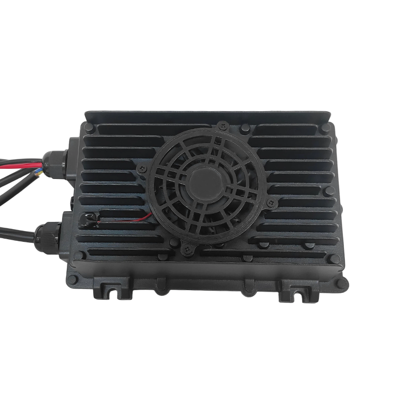
A comprehensive industrial vehicle on-board power system consists of several interconnected components, each serving a specific function in the power distribution and conversion chain.
Power Source and Storage
The primary power source in most industrial vehicle on-board systems originates from the vehicle's main battery bank or alternator. Modern systems employ multiple battery configurations, ranging from single lithium-ion units to multi-bank lead-acid arrays. Battery capacity typically ranges from 100 to 800 ampere-hours, depending on application requirements and runtime expectations.
Energy storage acts as a buffer, allowing the system to maintain power output during idling periods or when engine load fluctuates. Premium systems incorporate battery management modules that monitor cell voltage, temperature, and state of charge in real-time.
Power Conversion and Regulation
The converter stage transforms raw battery voltage into regulated output suitable for sensitive equipment. DC-to-DC converters maintain stable voltage levels, typically stepping down from primary battery voltage (12V, 24V, or 48V) to specific requirements demanded by auxiliary loads.
Voltage regulation systems employ multiple topologies, including buck converters, boost converters, and isolation transformers. These devices incorporate advanced filtering to minimize voltage ripple and electromagnetic interference, protecting downstream equipment from electrical damage.
Inversion and AC Power Generation
For equipment requiring alternating current, on-board inverter technology converts DC voltage to 110V or 230V AC output at standard frequencies (50Hz or 60Hz). Modern inverters employ sophisticated PWM (Pulse Width Modulation) control circuits that synthesize clean sine-wave output, ensuring compatibility with sensitive electronic devices.
Inverter capacity ranges from 500W to 10kW in mobile applications, with efficiency ratings typically exceeding 90% under nominal loads.
Distribution and Protection Infrastructure
Safety systems within on-board power installations include circuit breakers, fuses, and surge protection devices positioned at critical junctures. Modern systems incorporate microprocessor-controlled protection that disconnects loads during fault conditions, preventing cascading failures.
Distribution panels route power through segregated circuits, each protecting specific equipment categories. This modular approach allows independent operation of separate systems without affecting overall power availability.
Primary Applications in Industrial Operations
Mobile Refrigeration and Climate Control
Refrigerated transport vehicles represent one of the largest consumer segments for on-board power systems. These installations must maintain constant compressor operation independent of vehicle engine state, requiring dedicated power supplies with capacity ratings of 2-5 kilowatts. System uptime exceeds 99.5% in modern implementations, critical for perishable goods preservation.
Mobile Workshop and Field Service Vehicles
Service technicians operating from mobile bases depend on stable power for diagnostic equipment, power tools, and communication systems. Typical installations provide 3-7 kilowatts of continuous power, enabling simultaneous operation of multiple high-draw devices. AC inverter capability allows direct connection of standard workshop equipment without modification.
Emergency Response and Rescue Operations
Emergency service vehicles require absolute power reliability for life-critical equipment. On-board power systems in these applications incorporate redundant power paths, multiple battery banks, and automatic switchover systems. Many installations maintain operating capacity sufficient for 48-72 hours of equipment operation during extended deployment.
Data Collection and Communications
Mobile surveillance platforms, weather monitoring stations, and telecommunications equipment mounted on vehicles demand consistent power delivery for 24/7 operation. Modern systems provide programmable output configurations, allowing simultaneous delivery of multiple voltage and current levels to diverse equipment.
Construction and Powered Equipment Support
Mobile crane operations, hydraulic pressure systems, and construction-site command centers require robust power infrastructure. On-board systems supporting these applications often exceed 10 kilowatts capacity, rivaling small portable generators in performance while offering superior reliability and reduced maintenance.
Technical Specifications and Performance Metrics
Understanding key performance parameters enables informed system selection and installation planning.
| Parameter | Typical Range | Industrial Standard |
|---|---|---|
| Input Voltage | 12V to 48V DC | 24V DC (most common) |
| Output Voltage Precision | ±1-3% regulation | ±1% (high-precision) |
| Frequency Stability | ±0.5-2 Hz | ±0.1 Hz (critical loads) |
| Power Capacity | 500W to 15kW | 2-8 kW (most installations) |
| Efficiency Rating | 85-95% | 92-95% (premium systems) |
| Response Time to Load Change | 10-50 milliseconds | 20-30 milliseconds |
| Operating Temperature Range | -10 to 60 degrees Celsius | -20 to 55 degrees Celsius |
| Isolation Voltage | 1500-3000V | 2000V (standard) |
Efficiency Considerations
System efficiency represents the percentage of input power successfully converted to usable output, with losses dissipating as heat. Modern converter technology achieves 93-96% efficiency under optimal operating conditions, significantly reducing fuel consumption compared to equivalent portable generator solutions.
Operating at partial load (50-75% of rated capacity) typically produces optimal efficiency in most converter designs. Full-load operation generates excess heat, while minimal loads operate less efficiently due to fixed switching losses.
Reliability and Mean Time Between Failures
Industrial-grade on-board power systems demonstrate mean time between failures (MTBF) exceeding 50,000 hours under proper operating conditions. This translates to decades of service life in typical vehicle applications where annual operating hours rarely exceed 2,000.
Failure analysis indicates that most system degradation results from thermal stress or inadequate maintenance rather than inherent component limitations. Proper thermal management and periodic filter replacement extend system lifespan significantly.
Selecting the Right On-Board Power System
Load Analysis and Power Demand Calculation
Proper system selection begins with comprehensive load analysis identifying all connected equipment and operating scenarios. Create detailed load inventories documenting:
- Equipment name and rated power consumption
- Duty cycle and simultaneous operation probability
- Starting current requirements (inrush current)
- Thermal dissipation characteristics
- Voltage and frequency sensitivity specifications
Most industrial applications should size systems at 125% of calculated peak load to accommodate unforeseen additions and ensure safe operating margins. Undersized systems operate continuously at maximum capacity, accelerating component degradation.
Input Voltage Compatibility
Standard industrial vehicle electrical systems operate at 12V, 24V, or 48V direct current. System selection must match available vehicle power supply voltage precisely. Many modern vehicles employ dual battery banks, requiring systems capable of managing independent voltage sources or automatic configuration switching.
Output Configuration Requirements
Determine whether connected equipment demands DC only, AC only, or mixed voltage/frequency outputs. Some applications require multiple isolated DC outputs at different voltage levels. Premium systems offer modular configuration allowing customization of output specifications.
Environmental and Spatial Constraints
Operating temperature ranges, vibration exposure, and moisture levels vary significantly between vehicle types and deployment regions. Confirm system specifications exceed environmental demands by adequate safety margins. Physical space limitations may require compact form factors, though this typically increases cost and may reduce cooling capability.
Redundancy and Failure Tolerance Requirements
Critical applications justify investment in redundant systems with automatic switchover capability. Multi-battery configurations allow continued operation even when individual battery units require replacement. Modular power distribution enables continued service to priority loads during component failure.
Installation and Integration Best Practices
Electrical Integration Steps
Proper installation requires careful attention to cable sizing, connector quality, and grounding topology. Undersized cables cause excessive voltage drop, reducing available power at equipment terminals. Industry standards recommend cable sizing based on current-carrying capacity and permissible voltage drop limits.
Thermal Pathway Design
Position power converters and inverters where natural airflow provides cooling. Avoid enclosures that restrict ventilation, as thermal buildup rapidly degrades component reliability. Most installations benefit from dedicated thermal management hardware: cooling fans, heat sinks, or thermally conductive enclosure materials.
Protective Device Coordination
Circuit protection must coordinate across multiple system levels. Primary disconnect switches prevent uncontrolled power drain when vehicles sit idle. Secondary branch circuit protection isolates individual loads or equipment groups. Surge protection at the input terminal defends against transient voltage spikes from alternator commutation or external lightning strikes.
System Monitoring and Control Architecture
Modern installations incorporate digital monitoring systems that log operational parameters and alert operators to anomalies. Remote monitoring capability enables predictive maintenance, allowing technicians to schedule service before component failure occurs. Data analysis reveals usage patterns, enabling optimization of battery charging strategies and load scheduling.
Maintenance and Troubleshooting
Preventive Maintenance Schedule
Systematic maintenance significantly extends on-board power system lifespan and prevents unexpected failures during critical operations. Key maintenance tasks include:
- Quarterly inspection of cable connections and terminal corrosion
- Semi-annual battery capacity testing and electrolyte level verification
- Annual thermal performance assessment and cooling fan inspection
- Triennial firmware updates and control system diagnostics
- Periodic load testing under actual operational conditions
Common Troubleshooting Scenarios
Insufficient Output Voltage
Voltage regulation failures typically result from loose connections, corroded terminals, or battery degradation. Systematic voltage measurements from source through distribution points identify where voltage drop occurs. Cable upsizing and connection re-termination usually resolve these issues.
Inverter Shutdown During Load Peaks
Starting current inrush from motor-driven equipment often exceeds steady-state current limits, triggering protective shutdown. Oversizing the inverter or implementing soft-start technology for connected motors eliminates this issue. Some loads require starting current headroom of 300-400% above steady-state requirements.
Excessive Temperature Rise
Thermal management failures indicate restricted airflow or component degradation. Inspect and clean cooling fans, remove debris from heat sinks, and verify thermal paste integrity on semiconductor mounting surfaces. Continuous operation above thermal limits accelerates component failure.
Battery Discharge During Extended Idle Periods
Parasitic drain from monitoring systems and auxiliary devices discharges batteries during extended vehicle parking. Modern systems employ low-power sleep modes and load disconnection timers to minimize idle drain. Replacement of defective parasitic load circuits restores normal behavior.
Emerging Technologies and Future Development
Advanced Battery Chemistry
Lithium iron phosphate (LiFePO4) battery technology increasingly replaces traditional lead-acid alternatives in premium on-board power installations. These systems offer three to five times longer lifespan, superior cold-weather performance, and integrated battery management electronics. Higher upfront costs justify themselves through extended service intervals and reduced replacement frequency.
Smart Power Distribution Systems
Artificial intelligence and machine learning algorithms optimize power allocation based on real-time load patterns and historical usage data. Predictive algorithms anticipate peak demand periods, pre-charging batteries and scheduling maintenance during low-utilization windows. Network connectivity enables remote diagnostics and automatic alert generation when system degradation exceeds thresholds.
Renewable Energy Integration
Solar charging modules increasingly integrate with vehicle-mounted power systems, supplementing generator output during daylight hours. Hybrid systems combining solar, alternator, and battery power optimize efficiency and reduce fuel consumption. Charge controllers automatically select optimal power sources based on availability and cost factors.
Modular Architecture Evolution
Future systems emphasize plug-and-play modularity, allowing users to upgrade individual components without replacing entire assemblies. Standardized interfaces enable rapid customization for changing application requirements, reducing downtime during technology transitions.
Key Advantages Over Traditional Power Solutions
| Criteria | On-Board Power System | Portable Generator |
|---|---|---|
| Space Efficiency | Compact, integrated design | Requires dedicated area |
| Maintenance Requirements | Minimal (quarterly) | Substantial (monthly) |
| Noise Level | Silent operation | 85-95 decibels |
| Environmental Impact | Zero direct emissions | Fossil fuel combustion |
| Operational Cost | Low fuel consumption | High fuel consumption |
| Installation Complexity | Moderate (integrated) | Simple (standalone) |
| Reliability During Cold Weather | Excellent | Compromised |
Economic Impact Analysis
Total cost of ownership (TCO) calculations demonstrate that on-board power systems achieve cost parity with portable generators within 3-5 years of operation, depending on utilization intensity. Extended lifespan (15-20+ years versus 5-10 years) and minimal maintenance requirements produce substantial lifetime savings.
Fuel efficiency advantages become particularly pronounced in applications requiring extended idle-power delivery, where on-board battery power eliminates engine fuel consumption entirely. Commercial operations report fuel cost reductions of 30-50% after installing on-board power systems.
Frequently Asked Questions
Q1: Can an on-board power system operate independently from the vehicle engine?
Yes, modern on-board power systems include dedicated battery banks that enable equipment operation even when the engine is off. Battery capacity determines runtime duration, typically ranging from 2-48 hours depending on load consumption and battery size. Most systems automatically switchover to engine-driven charging when battery reserve capacity drops below defined thresholds.
Q2: What is the typical lifespan of an industrial vehicle on-board power system?
Premium on-board power systems demonstrate operational lifespan exceeding 15-20 years with proper maintenance. Lead-acid battery components typically require replacement every 5-7 years, while lithium-based systems extend battery life to 10-15 years. Converter and inverter components rarely fail within normal product lifespans when operating within design specifications.
Q3: How much weight does an on-board power system add to a vehicle?
Total system weight varies significantly based on capacity and battery chemistry. Typical installations range from 200-800 kilograms, with battery weight comprising the majority. Lithium battery systems weigh 40-50% less than equivalent lead-acid configurations, though cost premiums often exceed weight savings justification for many applications.
Q4: Can existing vehicles retrofit on-board power systems, or are custom installations required?
Most vehicle types accommodate aftermarket on-board power installations, though customization requirements vary. Vehicles with sufficient under-chassis space support straightforward battery and converter placement. Tight installations may require custom mounting brackets and cable routing, increasing labor costs by 20-40% compared to OEM installations.
Q5: What protection mechanisms prevent on-board power systems from discharging vehicle starting batteries?
Integrated isolation relays and smart distribution systems prevent auxiliary power draw from compromising engine starting capability. Battery management electronics maintain reserve capacity thresholds, automatically disconnecting non-critical loads when overall battery voltage approaches minimum engine start requirements. Dual battery configurations eliminate this concern entirely by segregating starting and auxiliary power sources.
Q6: How do on-board power systems handle sudden load fluctuations or equipment failures?
Advanced control systems detect abnormal current draw patterns within milliseconds and initiate protective shutdown of affected circuits. Load shedding algorithms prioritize critical equipment, disconnecting lower-priority devices to prevent system-wide voltage collapse. Most modern systems recover full functionality within 5-10 seconds as control algorithms re-enable protected circuits following fault resolution.
Q7: Are on-board power systems compatible with standard 110V/230V equipment without modification?
Yes, inverter-equipped systems generate standard utility-grade AC power compatible with conventional equipment. However, equipment with very high starting current requirements may exceed inverter capacity. Most power tools, HVAC systems, and laboratory instruments operate without modification, though oversized industrial equipment may require system upgrades or soft-start technology implementation.
Q8: What monitoring capabilities do modern on-board power systems provide?
Digital monitoring systems track voltage, current, frequency, temperature, and battery state-of-charge in real-time. Data logging creates historical records enabling trend analysis and predictive maintenance scheduling. Remote connectivity options allow smartphone access to system status, enabling operators to adjust settings or receive alerts from anywhere. Some systems integrate with vehicle telematics platforms for centralized fleet management.
For exclusive deals and latest offers, sign up by entering your email address below.

CONTACT
- 88 Chuangye Street, Qingshanhu Street, Lin 'an District, Hangzhou City, Zhejiang, China
- fldz@fengletech.com
- +86-571-61097576
- +86-13721109386
- +86-15067105688
NEWSLETTER
Contact us today to get your exclusive solution and quote.
We promise never to disclose your privacy.
Copyright © Hangzhou Fengle Electronic Technology Co., Ltd. All Rights Reserved
Custom Forklift Electrical Parts Manufacturers
